Ambilight
Difficulty Level: Advanced
Reading Time: Minutes
Introduction
When I was looking around trying to get this all working, I read in several places that this project required an Arduino. Well, I am here to tell you it does not. In fact, the Arduino added an entirely new level of frustration.
Let’s begin with the required parts:
Hardware
- Raspberry Pi 3 Model B
- Case (e.g., Argon Fan Hat)
- SD Card (8GB should be plenty)
- HDMI Splitter
- USB HDMI Video Capture
- 100 Ohm Resistor
- WS2812B LED Strip
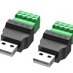
- USB Breakout Block
- 5 Volt Switching Power Supply (ensure sufficient wattage for your LEDs)
Software
- Hyperbian
- Balena Etcher
Step 1: Setup LED Strip
Attach the LED strip around the back of your TV, ensuring the lights face the wall to reflect properly. Multiple methods exist for managing corners; I simply folded my strip over and continued the line. Start the strip at the bottom left (when facing the front of the TV) and move clockwise.
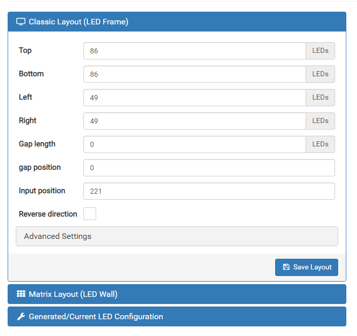
Count the LEDs on each side (e.g., 86 on top and bottom, 49 on each side). You will need this information later.
Step 2: Install Hyperbian
- Download the latest Hyperbian image and flash it to your SD card using Balena Etcher:
- Launch Balena Etcher.
- Select the Hyperbian image you downloaded.
- Choose the SD card as the destination (note: this will erase all data on the card).
- Click "Flash" to write the image.
- After flashing, two new partitions will appear on your system. Open the writable partition labeled "BOOT" and:
- Create a file named
sshwith a single space in it (no extension). - Create another file named
wpa_supplicant.confwith the following contents:
country=US ctrl_interface=DIR=/var/run/wpa_supplicant GROUP=netdev update_config=1 network={ ssid="" psk=" " } - Create a file named
- Insert the SD card into the Raspberry Pi and power it up with a reliable power supply.
Step 3: Configure Hyperion
- Find the IP address of your Raspberry Pi (check your router’s DHCP table or use tools like Angry IP).
- Open a browser and navigate to
http://IP_ADDRESS:8090to access the Hyperion configuration screen. - Go to the Configuration tab. Below are my recommended settings:
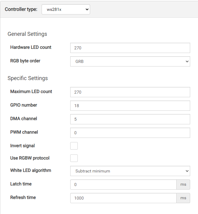
LED Hardware Settings
LED Controller:
LED Layout: Enter the number of LEDs for each side of your TV. Adjust the gap and input position as needed. If no gaps exist, setup is simpler.
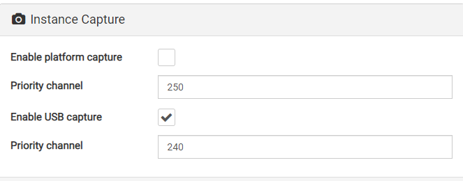
Capturing Hardware Tab
Configure the settings to match your setup. Experiment with the configuration until it works correctly.
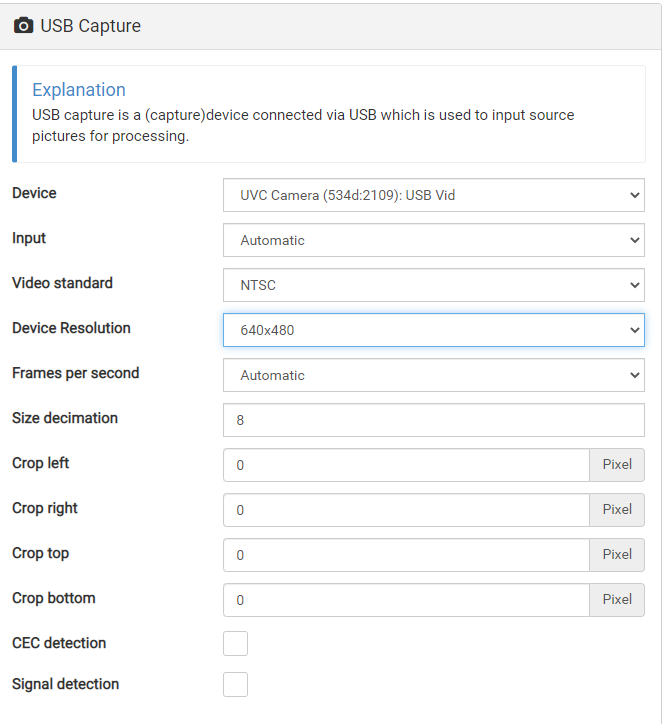
Step 4: Hooking It All Up
The overall flow of the setup looks like this:
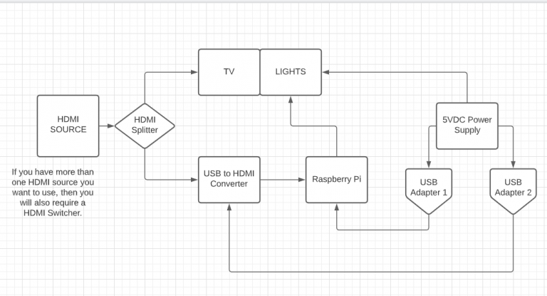
Wiring the LEDs
Connect the LEDs to the power supply and the Raspberry Pi. Solder a 100-ohm resistor inline with the data line and use a quick-connect plug for easier connection to the LED strip.
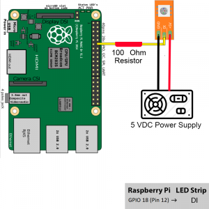
Powering the Pi and Splitter
Only thing remaining is powering the Pi and Splitter. You can do this any way you want. You may power the splitter off of the Pi and then use a good quality power supply for the Pi. I used a USB terminal block as shown here:
Wiring:
- The left terminal (Pin 4) is the ground from the power supply.
- The right terminal (Pin 1) is the +5VDC from the power supply.
I installed two of these and connected everything to them.
That’s it! Not much to it. This project should take about an hour—give or take 4 days!
